


1. 什麼是 GoBGP?
GoBGP 是使用 Go 語言開發的,運行在 Linux 系統上的開源工具,可以提供 BGP 協議的控制平面功能。與 Quagga/FRRouting 相比,GoBGP 的性能更好,收斂時間更短,可以適用於更大規模的網絡,比如充當 IXP 路由器:

[圖1. GoBGP Performance]
GoBGP 僅支持 BGP 這一種路由協議,但是它可以和 Zebra 集成,通過 API 的方式與 Quagga/FRR 協同工作,以支持多種路由協議。
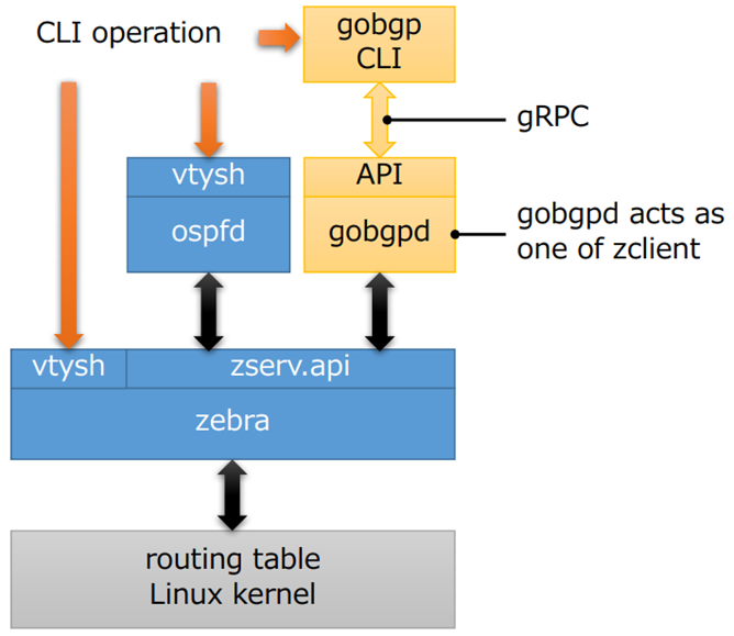
[圖2. GoBGP Architecture]
可以使用 Python、C++ 等多種語言,通過 gRPC API 對 GoBGP 進行配置,當然也支持 CLI。GoBGP 還支持 OpenConfig,其 YANG 模型符合 draft-ietf-idr-bgp-model-03。
因爲 GoBGP 可以很方便地人工干涉路由,參與感更強,是一個很好的實驗工具。本文就利用 GoBGP 和 Cisco NXOSv 搭建實驗環境,來學習 VXLAN EVPN 的一些原理。
2. 安裝 GoBGP
GoBGP 的安裝非常簡單,從 https://github.com/osrg/gobgp/releases 下載 tar.gz 文件,解壓即可。在元旦之前,GoBGP 剛剛 Release 了 v2.0.0。
Java
|
1 |
$ tar -xzf gobgp_2.0.0_linux_amd64.tar.gz |
解壓之後可以看到 2 個可執行文件:gobgp 和 gobgpd。其中 gobgp 是 gRPC 的 CLI client 工具,gobgpd 是 GoBGP 主程序。
Java
|
1 2 3 4 5 6 7 |
$ ls -l total 40740 -rwxrwxr-x. 1 chengc2 chengc2 14386512 Dec 30 05:17 gobgp -rw-rw-r--. 1 chengc2 chengc2 11299444 Jan 12 23:13 gobgp_2.0.0_linux_amd64.tar.gz -rwxrwxr-x. 1 chengc2 chengc2 16005264 Dec 30 05:18 gobgpd -rw-rw-r--. 1 chengc2 chengc2 11324 Jun 8 2017 LICENSE -rw-rw-r--. 1 chengc2 chengc2 2412 Dec 24 01:14 README.md |
如果使用源代碼方式安裝,可以獲取最新的 master branch,但是要複雜一些。
首先安裝 Golang。從 https://golang.org/dl 下載 binary release,需要 1.11 或更高版本,解壓到 /usr/local 目錄:
Java
|
1 |
$ sudo tar -C /usr/local -xzf go1.11.4.linux-amd64.tar.gz |
然後設置環境變量:
Java
|
1 2 3 4 5 6 7 8 9 10 11 12 13 14 15 16 17 |
# Ubuntu修改$HOME/.profile $ sudo vi $HOME/.profile
# CentOS修改/etc/profile $ sudo vi /etc/profile
# 在profile文件底部增加2行: export GOPATH=$HOME/go export PATH=$PATH:/usr/local/go/bin
$ mkdir $HOME/go
# Ubuntu使profile立即生效: $ source $HOME/.profile
# CentOS使profile立即生效: $ source /etc/profile |
最後 go get 兩個 binary 文件:
Java
|
1 2 |
$ go get github.com/osrg/gobgp/gobgp $ go get github.com/osrg/gobgp/gobgpd |
如果無法直接訪問境外的服務器,源代碼安裝很容易失敗。所以還是建議使用 binary release。
3. 準備 Cisco 網絡環境
在繼續實驗之前,先按照下面的拓撲準備好 Cisco 的網絡環境。本次實驗採用 iBGP,僅配置 l2vpn evpn address-family。
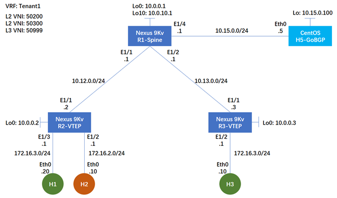
[圖3. Topology]
3.1 R1-Spine 設備配置
Java
|
1 2 3 4 5 6 7 8 9 10 11 12 13 14 15 16 17 18 19 20 21 22 23 24 25 26 27 28 29 30 31 32 33 34 35 36 37 38 39 40 41 42 43 44 45 46 47 48 49 50 51 52 53 54 55 56 57 58 59 60 61 62 63 64 65 66 67 68 69 |
# 開啓相關feature nv overlay evpn feature ospf feature bgp feature pim feature vn-segment-vlan-based feature nv overlay
# 配置Rendezvous Point ip pim rp-address 10.0.10.1 group-list 224.0.0.0/4 ip pim ssm range 232.0.0.0/8
interface Ethernet1/1 description to R2 mtu 9000 # ESXi Standard Switch的MTU最大9000 mac-address 000c.2915.3243 # NXOSv需要手工配置L3接口MAC ip address 10.12.0.1/24 ip ospf network point-to-point ip router ospf 1 area 0.0.0.0 ip pim sparse-mode no shutdown
interface Ethernet1/2 description to R3 mtu 9000 mac-address 000c.2915.3244 ip address 10.13.0.1/24 ip ospf network point-to-point ip router ospf 1 area 0.0.0.0 ip pim sparse-mode no shutdown
interface Ethernet1/4 description to H5-GoBGP mtu 9000 mac-address 000c.2915.3246 ip address 10.15.0.1/24 ip router ospf 1 area 0.0.0.0 ip pim sparse-mode no shutdown
interface loopback0 ip address 10.0.0.1/32 ip router ospf 1 area 0.0.0.0 ip pim sparse-mode
interface loopback10 description PIM-RP # 也可以用Loopback0作爲RP ip address 10.0.10.1/32 ip router ospf 1 area 0.0.0.0 ip pim sparse-mode
router ospf 1 router-id 10.0.0.1 router bgp 65000 router-id 10.0.0.1 template peer LEAF # 配置peer模板 remote-as 65000 update-source loopback0 address-family l2vpn evpn # 本次實驗不需要配置 IPv4 AF send-community send-community extended route-reflector-client # 啓用RR neighbor 10.0.0.2 inherit peer LEAF # 讓peer繼承模板 neighbor 10.0.0.3 inherit peer LEAF neighbor 10.15.0.100 inherit peer LEAF |
3.2 R2-VTEP & R3-VTEP 設備配置
Java
|
1 2 3 4 5 6 7 8 9 10 11 12 13 14 15 16 17 18 19 20 21 22 23 24 25 26 27 28 29 30 31 32 33 34 35 36 37 38 39 40 41 42 43 44 45 46 47 48 49 50 51 52 53 54 55 56 57 58 59 60 61 62 63 64 65 66 67 68 69 70 71 72 73 74 75 76 77 78 79 80 81 82 83 84 85 86 87 88 89 90 91 92 93 94 95 96 97 98 99 100 101 102 103 104 105 106 107 108 |
nv overlay evpn feature ospf feature bgp feature pim feature interface-vlan feature vn-segment-vlan-based feature nv overlay
fabric forwarding anycast-gateway-mac 0001.0001.0001 # 爲Anycast GW配置MAC地址 ip pim rp-address 10.0.10.1 group-list 224.0.0.0/4 ip pim ssm range 232.0.0.0/8 vlan 1,200,300,999 # 本次實驗爲R3-VTEP配置3個不同的VLAN:vlan 1,288,388,888 vlan 200 # R3-VTEP爲vlan 288 name L2-VNI-50200-Tenant1 vn-segment 50200 # 將VNI和VLAN綁定 vlan 300 # R3-VTEP爲vlan 388 name L2-VNI-50300-Tenant1 vn-segment 50300 vlan 999 # R3-VTEP爲vlan 888 name L3-VNI-50999-Tenant1 vn-segment 50999
#因爲GoBGP+Cisco異構部署,且需要人工發佈路由,所以本次測試採用靜態RD和RT vrf context Tenant1 vni 50999 rd 50999:1 address-family ipv4 unicast route-target import 50999:1 route-target import 50999:1 evpn route-target export 50999:1 route-target export 50999:1 evpn
interface Vlan200 # R3-VTEP爲vlan 288 no shutdown vrf member Tenant1 ip address 172.16.2.1/24 fabric forwarding mode anycast-gateway
interface Vlan300 # R3-VTEP爲vlan 388 no shutdown vrf member Tenant1 ip address 172.16.3.1/24 fabric forwarding mode anycast-gateway
interface Vlan999 # R3-VTEP爲vlan 888 no shutdown vrf member Tenant1 ip forward
interface nve1 no shutdown host-reachability protocol bgp source-interface loopback0 member vni 50200 mcast-group 239.0.0.1 member vni 50300 mcast-group 239.0.0.1 member vni 50999 associate-vrf
interface Ethernet1/1 description to R1 mtu 9000 mac-address 000c.2964.0299 # R3-VTEP配置:mac-address 000c.29c7.522e ip address 10.12.0.2/24 # R3-VTEP配置:ip address 10.13.0.3/24 ip ospf network point-to-point ip router ospf 1 area 0.0.0.0 ip pim sparse-mode no shutdown
interface Ethernet1/2 switchport switchport access vlan 200 # R3-VTEP配置:switchport access vlan 388 no shutdown
interface Ethernet1/3 # R3-VTEP沒有配置這個接口 switchport switchport access vlan 300 no shutdown
interface loopback0 ip address 10.0.0.2/32 # R3-VTEP配置:ip address 10.0.0.3/32 ip router ospf 1 area 0.0.0.0 ip pim sparse-mode
router ospf 1 router-id 10.0.0.2 # R3-VTEP配置:router-id 10.0.0.3 router bgp 65000 router-id 10.0.0.2 # R3-VTEP配置:router-id 10.0.0.3 neighbor 10.0.0.1 remote-as 65000 update-source loopback0 address-family l2vpn evpn send-community send-community extended vrf Tenant1 address-family ipv4 unicast advertise l2vpn evpn
#因爲GoBGP+Cisco異構部署,且需要人工發佈路由,所以本次測試採用靜態RD和RT evpn vni 50200 l2 rd 50200:1 route-target import 50200:1 route-target export 50200:1 vni 50300 l2 rd 50300:1 route-target import 50300:1 route-target export 50300:1 |
然後用 3 個 Puppy Linux 分別作爲 H1,H2 和 H3。從 H2 ping H3,可以 ping 通:
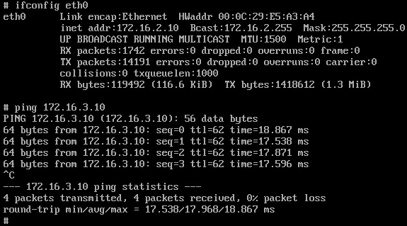
[圖4. H2_ping_H3]
從 H1 ping H3 和 H2,也都可以 ping 通:
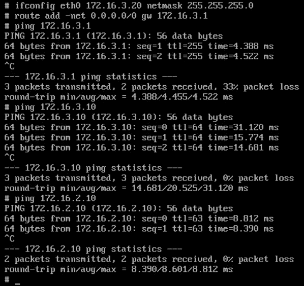
[圖5. H1_ping_H3&H2]
4. Symmetric IRB
您應該注意到了,雖然我爲 2 個 VTEP R2 和 R3 配置了相同的 L2VNI 和 L3VNI,但是我爲它們配置了不同的 VLAN ID。R2 的 3 個 VLAN ID 分別爲 200、300、999,而 R3 的 3 個 VLAN ID 分別爲 288、388、888。這並不影響 VXLAN 網絡的連通性,3 臺 Host 都可以互相 ping 通。
draft-ietf-bess-evpn-inter-subnet-forwarding 定義了 2 種 IRB 操作模型,Asymmetric IRB 和 Symmetric IRB,Cisco Nexus 採用的是後一種。在 Symmetric IRB 模型中,Tenant System 1 的流量抵達 Ingress VTEP 之後,先在 Bridge Table 查找 ARP,然後進入 IP-VRF 查找路由表,再封裝 L3VNI 傳遞給 Egress VTEP。流量抵達 Egress VTEP,解封裝 L3VNI,在 IP-VRF 查找路由表,然後在 Bridge Table 查找 ARP,最後發給本地的 Tenant System。下圖是流量的傳輸路徑:

圖6. Symmetric IRB
現在我們檢查一下 VTEP 的 ARP 表:
Java
|
1 2 3 4 5 6 7 8 9 10 11 12 13 14 15 16 17 18 |
R2-VTEP# show ip arp vrf Tenant1
...(snip)
IP ARP Table for context Tenant1 Total number of entries: 2 Address Age MAC Address Interface Flags 172.16.3.20 00:00:48 000c.2996.007a Vlan300 172.16.2.10 00:00:27 000c.298c.0cfa Vlan200
R3-VTEP# show ip arp vrf Tenant1
...(snip)
IP ARP Table for context Tenant1 Total number of entries: 1 Address Age MAC Address Interface Flags 172.16.3.10 00:00:48 000c.2936.0159 Vlan388 |
在 ARP 表裏面有 VLAN ID 的信息,H1 和 H3 雖然位於相同的子網,但是在 R2 和 R3 的 ARP 表中,VLAN ID 並不相同。這並沒有關係,因爲 ARP 表是本地有效的。
再檢查一下 VTEP 的 Bridge 表,請注意第 2 條 entry,這是 H3 的 Bridge 信息。Topology 是本地的 VLAN ID,採用的協議是 BGP 而不是 Local,下一跳是 R3-VTEP 的 IP 而不是本地的接口。這意味着 Intra-Subnet 的流量如果需要跨越不同的 VTEP,也要通過 EVPN 路由。只不過這不涉及到 Symmetric IRB Model,封裝的 VNI 是 L2VNI。
Java
|
1 2 3 4 5 6 7 8 9 10 11 |
R2-VTEP# show l2route evpn mac all
...(snip)
Topology Mac Address Prod Flags Seq No Next-Hops ----------- -------------- ------ ------------- ---------- ---------------- 200 000c.298c.0cfa Local L, 0 Eth1/2 300 000c.2936.0159 BGP SplRcv 0 10.0.0.3 300 000c.2996.007a Local L, 0 Eth1/3 999 000c.298d.eb0a VXLAN Rmac 0 10.15.0.100 999 000c.29c7.522d VXLAN Rmac 0 10.0.0.3 |
再檢查一下 VTEP 的路由表:
Java
|
1 2 3 4 5 6 7 8 9 10 |
R2-VTEP(config-if)# show ip route vrf Tenant1
...(snip)
172.16.3.10/32, ubest/mbest: 1/0 *via 10.0.0.3%default, [200/0], 01:13:54, bgp-65000, internal, tag 65000 (ev pn) segid: 50999 tunnelid: 0xa000003 encap: VXLAN 172.16.3.20/32, ubest/mbest: 1/0, attached *via 172.16.3.20, Vlan300, [190/0], 00:31:39, hmm |
請注意 172.16.3.10/32 這條路由,下一跳是 R3-VTEP,vn-segment(segid)是 50999。如果是 Inter-Subnet 的流量跨越不同的 VTEP,需要通過 EVPN 路由並符合 Symmetric IRB 模型,封裝 L3VNI。
無論是 Intra-Subnet 還是 Inter-Subnet,VLAN ID 都是本地有效的。所以在配置 Cisco Nexus 交換機的時候,每一臺 VTEP 都可以單獨規劃 VLAN ID 和 VNI 和 VRF 的 mapping 關係 —— 雖然在 Cisco Nexus 交換機的配置文件中,VNI 必須配置在 VLAN 下面,但這並不意味着整個 Fabric 的 VNI 數量就受限於 VLAN ID 的數量。
5. GoBGP 和 NXOSv 建立 BGP EVPN Neighbor
GoBGP 可以通過 CLI 來建立 Neighbor,也可以採用配置文件的方式。我們先來創建一個名稱爲 gobgpd.conf 的配置文件:
Java
|
1 2 3 4 5 6 7 8 9 10 11 12 13 |
[global.config] as = 65000 router-id = "10.0.0.5"
[[neighbors]] [neighbors.config] neighbor-address = "10.0.0.1" peer-as = 65000 [[neighbors.afi-safis]] [neighbors.afi-safis.config] afi-safi-name = "l2vpn-evpn" [neighbors.transport.config] local-address = "10.15.0.100" |
其中 10.15.0.100 是 H5 的 lo 接口地址。如果不採用 Loopback 接口建立 Neighbor,則不需要在配置文件中寫入 neighbors.transport.config 字段。
然後啓動 gobgpd,同時開啓 debug:
Java
|
1 2 3 4 5 6 7 8 9 10 11 12 13 14 15 16 17 18 19 |
$ sudo ./gobgpd -f gobgpd.conf -l debug -p INFO[0000] gobgpd started INFO[0000] Finished reading the config file Topic=Config INFO[0000] Peer 10.0.0.1 is added INFO[0000] Add a peer configuration for:10.0.0.1 Topic=Peer DEBU[0000] IdleHoldTimer expired Duration=0 Key=10.0.0.1 Topic=Peer DEBU[0000] state changed Key=10.0.0.1 Topic=Peer new=BGP_FSM_ACTIVE old=BGP_FSM_IDLE reason=idle-hold-timer-expired DEBU[0010] state changed Key=10.0.0.1 Topic=Peer new=BGP_FSM_OPENSENT old=BGP_FSM_ACTIVE reason=new-connection DEBU[0010] state changed Key=10.0.0.1 Topic=Peer new=BGP_FSM_OPENCONFIRM old=BGP_FSM_OPENSENT reason=open-msg-received INFO[0010] Peer Up Key=10.0.0.1 State=BGP_FSM_OPENCONFIRM Topic=Peer DEBU[0010] state changed Key=10.0.0.1 Topic=Peer new=BGP_FSM_ESTABLISHED old=BGP_FSM_OPENCONFIRM reason=open-msg-negotiated DEBU[0011] received update
...(snip)
# GoBGP會自動發送keepalive: DEBU[0190] sent Key=10.0.0.1 State=BGP_FSM_ESTABLISHED Topic=Peer data="&{{[] 19 4} 0x12abc40}"
...(snip) |
在 R1-Spine 可以觀察到 Neighbor 已經 Up:
Java
|
1 2 3 4 5 6 7 8 |
R1-Spine# show bgp l2vpn evpn sum
...(snip)
Neighbor V AS MsgRcvd MsgSent TblVer InQ OutQ Up/Down State/PfxRcd 10.0.0.2 4 65000 556 465 331 0 0 06:42:22 4 10.0.0.3 4 65000 533 476 331 0 0 06:42:17 2 10.15.0.100 4 65000 283 312 331 0 0 01:24:19 0 |
新開一個 SSH 窗口,使用./gobgp neighbor 可以觀察到 R1-Spine 已成爲鄰居並且狀態是 Up:
Java
|
1 2 3 |
$ ./gobgp nei Peer AS Up/Down State |#Received Accepted 10.0.0.1 65000 00:52:58 Establ | 6 6 |
使用 ./gobgp global rib -a evpn 命令可以觀察到 GoBGP 收到了 NXOS 發來的完整的 EVPN 路由表。
請注意:不能用 Ctrl+C 終止 gobgpd 的屏幕輸出,否則進程也會終止。NXOS 會觀察到 Neighbor 狀態變爲 Idle,運行 gobgp 之後會提示 gRPC error:
Java
|
1 2 |
$ ./gobgp global rib failed to connect to 127.0.0.1:50051 over gRPC: context deadline exceeded |
6. Route-Type 2: MAC/IP Advertisement Route
接下來我們利用 GoBGP 向 NXOS 發送 RT-2 路由更新。RT-2 路由的作用是向 Fabric 通告 MAC/IP 的位置。根據 RFC-7432,RT-2 的 NLRI 格式如下:
Java
|
1 2 3 4 5 6 7 8 9 10 11 12 13 14 15 16 17 18 19 |
+---------------------------------------+ | RD (8 octets) | +---------------------------------------+ |Ethernet Segment Identifier (10 octets)| +---------------------------------------+ | Ethernet Tag ID (4 octets) | +---------------------------------------+ | MAC Address Length (1 octet) | +---------------------------------------+ | MAC Address (6 octets) | +---------------------------------------+ | IP Address Length (1 octet) | +---------------------------------------+ | IP Address (0, 4, or 16 octets) | +---------------------------------------+ | MPLS Label1 (3 octets) | +---------------------------------------+ | MPLS Label2 (0 or 3 octets) | +---------------------------------------+ |
在 VXLAN 場景,MPLS Label 就是 VNI,第 1 個是 L2VNI,第 2 個是 L3VNI。GoBGP 發送 RT-2 的命令格式爲:
Java
|
1 |
$ gobgp global rib -a evpn add macadv <mac address> <ip address> [origin { igp | egp | incomplete }] [esi <esi>] etag <etag> label <label> rd <rd> [rt <rt>...] [encap <encap type>] [router-mac <mac address>] [default-gateway] |
其中 ESI 和 Etag 的 Value 應該是什麼呢?我們先來看看 NXOS 向鄰居通告的路由信息是怎樣的:
Java
|
1 2 3 4 5 6 7 8 9 10 11 12 13 14 15 16 17 18 |
R2-VTEP# show bgp l2vpn evpn neighbors 10.0.0.1 advertised-routes
...(snip)
Network Next Hop Metric LocPrf Weight Path Route Distinguisher: 50200:1 (L2VNI 50200) *>l[2]:[0]:[0]:[48]:[000c.298c.0cfa]:[0]:[0.0.0.0]/216 10.0.0.2 100 32768 i *>l[2]:[0]:[0]:[48]:[000c.298c.0cfa]:[32]:[172.16.2.10]/272 10.0.0.2 100 32768 i
Route Distinguisher: 50300:1 (L2VNI 50300) *>l[2]:[0]:[0]:[48]:[000c.2996.007a]:[0]:[0.0.0.0]/216 10.0.0.2 100 32768 i *>l[2]:[0]:[0]:[48]:[000c.2996.007a]:[32]:[172.16.3.20]/272 10.0.0.2 100 32768 i
Route Distinguisher: 50999:1 (L3VNI 50999) |
R2-VTEP 連接了 2 個 Host,H1 和 H2,分別位於 2
個不同的 Subnet,對應 2 個不同的 L2VNI。它爲每個 Host 向每個 L2 RD 通告了 2 條路由:一條通告 MAC,用於 Bridging;另外一條通告 MAC/IP,用於 Routing。然後我們再觀察每個 MAC 對應的路由詳細內容:
Java
|
1 2 3 4 5 6 7 8 9 10 11 12 13 14 15 16 17 18 19 20 21 22 23 24 25 26 27 28 29 30 31 32 33 34 35 |
R2-VTEP# show bgp l2vpn evpn 000c.298c.0cfa BGP routing table information for VRF default, address family L2VPN EVPN Route Distinguisher: 50200:1 (L2VNI 50200) BGP routing table entry for [2]:[0]:[0]:[48]:[000c.298c.0cfa]:[0]:[0.0.0.0]/216, version 301 Paths: (1 available, best #1) Flags: (0x000102) (high32 00000000) on xmit-list, is not in l2rib/evpn Multipath: iBGP
Advertised path-id 1 Path type: local, path is valid, is best path AS-Path: NONE, path locally originated 10.0.0.2 (metric 0) from 0.0.0.0 (10.0.0.2) Origin IGP, MED not set, localpref 100, weight 32768 Received label 50200 Extcommunity: RT:50200:1 ENCAP:8
Path-id 1 advertised to peers: 10.0.0.1 BGP routing table entry for [2]:[0]:[0]:[48]:[000c.298c.0cfa]:[32]:[172.16.2.10] /272, version 90 Paths: (1 available, best #1) Flags: (0x000102) (high32 00000000) on xmit-list, is not in l2rib/evpn Multipath: iBGP
Advertised path-id 1 Path type: local, path is valid, is best path AS-Path: NONE, path locally originated 10.0.0.2 (metric 0) from 0.0.0.0 (10.0.0.2) Origin IGP, MED not set, localpref 100, weight 32768 Received label 50200 50999 Extcommunity: RT:50200:1 RT:50999:1 ENCAP:8 Router MAC:000c.2964.0298
Path-id 1 advertised to peers: 10.0.0.1 |
用於 Bridging 的路由僅攜帶了 L2VNI 和 MAC VRF 的 RT,而用於 Routing 的路由則同時攜帶了 L2VNI、 L3VNI 以及 MAC VRF 和 IP VRF 的 RT,還有 NVE Tunnel 接口的 MAC。在路由信息中, [2]:[0]:[0]:[48] 的含義是:
- [2] :Route Type 2
- 第 1 個 [0] :Ethernet Segment Identifier
- 第 2 個 [0] :Ethernet Tag ID
- [48] :MAC 地址長度
從上面的 show 結果,我們可以知道正常的 RT-2 路由都應該包括哪些內容。我們先使用 GoBGP 向 Fabric 通告一個並不存在 Host(GoBGP 不支持將直連網段重分佈到 BGP。需要安裝 Quagga/FRR 然後通過 Zebra API 才能將直連路由或其他協議的路由重分佈到 BGP),MAC 地址爲 aa:bb:cc:dd:ee:ff,IP 地址爲 172.16.2.20,和 H2 屬於同一個子網:
Java
|
1 2 3 4 |
# 通告 MAC $ ./gobgp global rib -a evpn add macadv aa:bb:cc:dd:ee:ff 0.0.0.0 esi 0 etag 0 label 50200 rd 50200:1 rt 50200:1 encap vxlan # 通告 MAC/IP $ ./gobgp global rib -a evpn add macadv aa:bb:cc:dd:ee:ff 172.16.2.20 esi 0 etag 0 label 50200,50999 rd 50200:1 rt 50200:1 50999:1 encap vxlan router-mac 000c.298d.eb0a |
在 R2-VTEP 上可以觀察到已經收到這 2 條 RT-2 路由並加表:
Java
|
1 2 3 4 5 6 7 8 9 10 11 12 13 14 15 16 17 18 19 20 21 22 23 |
R2-VTEP# show bgp l2vpn evpn
...(snip)
Route Distinguisher: 50200:1 (L2VNI 50200) *>l[2]:[0]:[0]:[48]:[000c.298c.0cfa]:[0]:[0.0.0.0]/216 10.0.0.2 100 32768 i *>i[2]:[0]:[0]:[48]:[aabb.ccdd.eeff]:[0]:[0.0.0.0]/216 10.15.0.100 100 0 ? *>l[2]:[0]:[0]:[48]:[000c.298c.0cfa]:[32]:[172.16.2.10]/272 10.0.0.2 100 32768 i *>i[2]:[0]:[0]:[48]:[aabb.ccdd.eeff]:[32]:[172.16.2.20]/272 10.15.0.100 100 0 ? ...(snip)
R2-VTEP# show ip route vrf Tenant1 ...(snip)
172.16.2.20/32, ubest/mbest: 1/0 *via 10.15.0.100%default, [200/0], 00:11:28, bgp-65000, internal, tag 65000 (evpn) segid: 50999 tunnelid: 0xa0f0064 encap: VXLAN
...(snip) |
並且 R2-VTEP 已經和 H5-GoBGP 成功建立了 NVE Peer:
Java
|
1 2 3 4 5 |
R2-VTEP# show nve peers Interface Peer-IP State LearnType Uptime Router-Mac --------- --------------- ----- --------- -------- ----------------- nve1 10.0.0.3 Up CP 03:15:43 000c.29c7.522d nve1 10.15.0.100 Up CP 00:17:50 000c.298d.eb0a |
6.1 ARP 報文傳輸路徑
在 H2 上 ping 相同子網的 172.16.2.20,然後在 ESXi 上抓取 H2 的流量,發現 H2 發送 ARP 請求 172.16.2.20 的 MAC,但一直沒有收到 ARP Response。在 H5 上抓包,發現並沒有抓取到 ICMP 或 ARP 報文。
但是在 H3 上 ping 不同子網的 172.16.2.20,卻可以在 H5 上抓取到 ICMP 報文。從下面的截圖可以看到 ICMP 報文有 VXLAN 的報頭,目的 VTEP IP 是 10.15.0.100,因爲是 Inter-Subnet 的流量,所以封裝的 VNI 是 L3VNI 50999。然後 H5 向 R3 迴應了 ICMP 不可達:
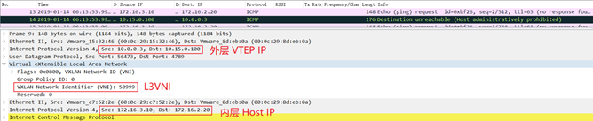
[圖7. H3_ICMP]
這是因爲在 H3 在請求 172.16.2.20 的 MAC 的時候,Anycast Gateway R3 會將自己的 MAC 迴應給 H3,也就是 fabric forwarding anycast-gateway-mac 0001.0001.0001 所配置的 MAC 地址:

[圖8. AnycastGW-ARP-Response]
而 H2 所請求的是相同子網的 MAC,雖然在 R2-VTEP 上存在去往 172.16.2.20 的 EVPN 路由,但爲了處理 BUM 流量,例如 ARP,R2-VTEP 需要將 ARP Request 用 VXLAN 封裝之後發往組播地址,本實驗我們所配置的組播地址是 239.0.0.1。其他 VTEP 收到 ARP Request 之後會解封裝並檢查所請求的地址是否在本地,如果不在本地則丟棄,如果在本地就發給目的主機,然後由目的主機單播回覆 ARP Response。
H5-GoBGP 並沒有辦法像 NXOS 那樣爲 L2VNI 指定一個組播地址加入組播組,所以它無法收到 ARP。我們採用一個變通的辦法,在 R1-Spine 上將連接 H5-GoBGP 的接口加入到組播組:
Java
|
1 2 3 |
interface Ethernet1/4 description to H5-GoBGP ip igmp join-group 239.0.0.1 |
然後在 H2 上 ping 172.16.2.20,就可以在 H5 上抓到 ARP Request 報文了:
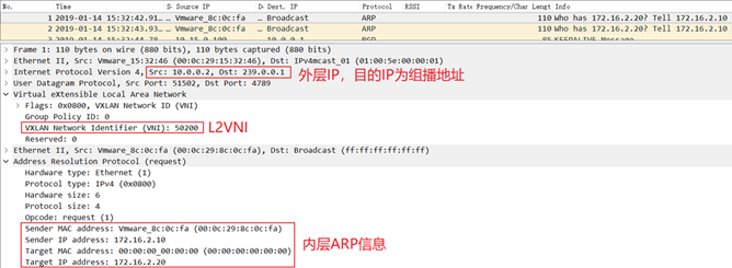
[圖9. ARP-Request]
在上面的截圖我們可以看到 VXLAN Outer 目的 IP 是 239.0.0.1。因爲是 Intra-Subnet 的流量,所以封裝的 VNI 是 L2VNI 50200。
當然也可以改用 BGP 而不使用組播的方式來複制 BUM,需要更改 int nve1 的配置:
Java
|
1 2 3 4 5 6 |
interface nve1 no shutdown host-reachability protocol bgp source-interface loopback0 member vni 50200 ingress-replication protocol bgp |
在沒有組播的情況下,就需要另外一種路由: Route Type 3 —— Inclusive Multicast Ethernet Tag route。每臺 VTEP 需要先向所有相關的 MAC VRF RD 通告 RT-3,告訴其他 VTEP 應該把 BUM 複製到哪裏,然後再按照上文介紹的流程通告 RT-2。
RT-3 NLRI 的格式如下:
Java
|
1 2 3 4 5 6 7 8 9 10 |
+---------------------------------------+ | RD (8 octets) | +---------------------------------------+ | Ethernet Tag ID (4 octets) | +---------------------------------------+ | IP Address Length (1 octet) | +---------------------------------------+ | Originating Router's IP Address | | (4 or 16 octets) | +---------------------------------------+ |
同時,BGP Extended Communities 必須要攜帶 RFC 6514 所定義的 Provider Multicast Service Interface (PMSI) Tunnel 屬性,以實現這種 Point-to-Multipoint 的複製。PMSI BGP 屬性的格式如下:
Java
|
1 2 3 4 5 6 7 8 9 |
+---------------------------------+ | Flags (1 octet) | +---------------------------------+ | Tunnel Type (1 octets) | +---------------------------------+ | MPLS Label (3 octets) | +---------------------------------+ | Tunnel Identifier (variable) | +---------------------------------+ |
其中 Flags 只定義了一種:Leaf Information Required (L)。在 VXLAN EVPN 的場景,Tunnel Type 的值是 6,表示這是 Ingress Replication。剩下 2 個字段就比較好理解了,分別是 VNI 和本地 NVE 接口的 IP 地址。
GoBGP 通告 RT-3 的 CLI 格式爲:
Java
|
1 |
$ gobgp global rib -a evpn add multicast <ip address> etag <etag> rd <rd> [rt <rt>...] [encap <encap type>] [pmsi <type> [leaf-info-required] <label> <tunnel-id>] |
其中 <ip address> 就是 Originating Router’s IP Address,而 <tunnel-id> 的值和 <ip address> 是一樣的,因爲 Cisco VTEP 只有 1 個 NVE 接口。我們可以在 GoBGP 上使用命令 gobgp global rib -a evpn 來看看 Cisco NXOSv 發給 GoBGP 的 RT-3 更新,比較一下 ip address 和 tunnel-id :

[圖9-2. GoBGP-RT-2]
在上面的截圖中,我們也可以看到 pmsi type 是 ingress-repl。
需要注意的是,GoBGP v1.3.3 在通告 RT-3 的時候會提示 runtime error,建議大家使用 v2.0.0 版本。
現在我們再回過頭來看看 Ethernet Segment Identifier 和 Ethernet Tag ID。
6.2 Ethernet Segment Identifier
我們知道數據中心爲了給服務器提供鏈路冗餘,通常會採用 2 臺 Leaf 堆疊的方式。但堆疊之後交換機升級會影響業務連續性,而且有可能會出現一些奇葩的問題。RFC-7432 提供了一種去堆疊的方式:EVPN multi-homing。
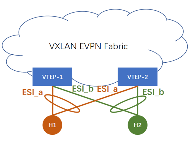
[圖10. EVPN_multihoming]
在 EVPN multi-homing 的場景,服務器正常 bonding 2 條 uplink,但 VTEP-1 和 VTEP-2 之間並沒有 peer-link,需要通過 EVPN Fabric 來交換信息。它們交換的就是 ESI 和 Etag。ESI 配置在每條 bundled link 上,如果相同 Domain 的 VTEP 有相同的 ESI,它們就會共享 multihomed neighbor。這種場景需要用到 Route Type 1 Auto-Discovery 路由。
本實驗的服務器都採用單掛,single-homing,所以 ESI 爲 0。
除了採用 ESI 來實現 multi-homing 之外,以阿里爲代表的國內互聯網公司正在使用另外一種去堆疊方式,Cisco 對應的技術是 VPC-less,即 VPC without peering link。
6.3 Ethernet Tag ID
Etag 的作用是在 EVPN Instance 中標識一個特定的廣播域(Bridge Table)。一個 EVPN Instance 就是一個 MAC-VRF,包含 1 個或多個 Bridge Table,這些 BT 共享相同的 Route Target。
在 Asymmetric IRB 模型中,1 個 MAC-VRF/EVI 會包含多個 BT。但是在 Symmetric IRB 操作模型中,1 個 MAC-VRF 僅包含 1 個 BT,是 1:1 的 mapping 關係,請看下面的 NXOS 相關配置:
Java
|
1 2 3 4 5 6 7 8 9 |
vlan 200 name L2-VNI-50200-Tenant1 vn-segment 50200
evpn vni 50200 l2 rd 50200:1 route-target import 50200:1 route-target export 50200:1 |
所以在 Symmetric IRB 模型中,Etag 必須置爲 0,不需要用它來區分廣播域。
7. Route-Type 5: IP Prefix Route
接下來我們讓 H5 作爲 EVPN Border,測試 RT-5 路由。由於 GoBGP 必須與 Quagga/FRR 的 Zebra API 集成,才能重分發外部路由到 BGP,所以這次實驗我們仍然只能用 1 個虛擬的 IP 地址作爲目的 IP。
GoBGP 通告 RT-5 的 CLI 格式是:
Java
|
1 |
$ ./gobgp global rib -a evpn add <ip prefix> [gw <gateway>] [origin { igp | egp | incomplete }] [esi <esi>] etag <etag> [label <label>] rd <rd> [rt <rt>...] [encap <encap type>] [router-mac <mac address>] |
從上文的分析中,我們已經知道 esi 和 etag 都爲 0。但是 gateway 又是怎麼回事?先不管這個,我們直接在 H5 向 Fabric 通告一條 RT-5:
Java
|
1 2 3 |
$ ./gobgp global rib -a evpn add prefix \ > 0.0.0.0/0 etag 0 label 50999 rd 50999:1 rt 50999:1 \ > encap vxlan router-mac 000c.298d.eb0a |
在 Cisco VTEP 可以觀察到已經收到了這條 RT-5 路由:
Java
|
1 2 3 4 5 6 7 8 9 10 11 12 13 14 15 16 17 18 19 20 21 22 23 |
R3-VTEP# sh bgp l2vpn evpn ...(snip)
Route Distinguisher: 50999:1 *>i[5]:[0]:[0]:[0]:[0.0.0.0]:[0.0.0.0]/224 10.15.0.100 100 0 ?
Route Distinguisher: 50999:1 (L3VNI 50999) *>i[2]:[0]:[0]:[48]:[000c.298c.0cfa]:[32]:[172.16.2.10]/272 10.0.0.2 100 0 i *>i[2]:[0]:[0]:[48]:[000c.2996.007a]:[32]:[172.16.3.20]/272 10.0.0.2 100 0 i *>i[5]:[0]:[0]:[0]:[0.0.0.0]:[0.0.0.0]/224 10.15.0.100 100 0 ?
R3-VTEP# sh ip route vrf Tenant1 ...(snip)
0.0.0.0/0, ubest/mbest: 1/0 *via 10.15.0.100%default, [200/0], 00:01:01, bgp-65000, internal, tag 65000 (evpn) segid: 50999 tunnelid: 0xa0f0064 encap: VXLAN
...(snip) |
在 H3 上 ping 一個路由表裏不存在的地址 100.100.100.100,然後可以在 H5 上抓取到這些 ICMP 報文,RT-5 路由生效了:
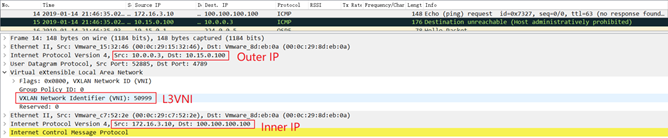
[圖11. RT-5_ICMP]
另外請注意 Inner MAC(我忘記用紅色框出來了),這是在 RT-2 和 RT-5 路由更新中所攜帶的 router-mac 屬性。VTEP 解封裝 VXLAN 數據包之後看到 Inner MAC 是自己的 Tunnel 接口地址,就會進一步地處理報文轉發。
H5-GoBGP 在通告 RT-5 路由的時候,並沒有攜帶 [gw <gateway>] 參數,那麼這個參數的作用是什麼呢?
上文已經談到 Cisco 採用的 Inter-Subnet 操作模型是 Symmetric IRB。在這個 IRB 模型中,Inter-Subnet 路由是 IP-VRF to IP-VRF。在 draft-ietf-bess-evpn-prefix-advertisement 中又定義了 3 種 IP-VRF-to-IP-VRF 模型,分別是:
- Interface-less IP-VRF-to-IP-VRF Model
- Interface-ful IP-VRF-to-IP-VRF with SBD IRB
- Interface-ful IP-VRF-to-IP-VRF with Unnumbered SBD IRB
7.1 Interface-less IP-VRF-to-IP-VRF Model
Cisco Nexus 採用的就是這種最簡單的模型,IP-VRF 直連 IP-VRF,不需要額外的 Overlay Index。正如我們剛纔所操作的那樣,在這種模型中,Border Node 只需要通告 1 條 RT-5 路由並且不需要攜帶 GW 參數,只需要攜帶 router-mac 參數把自己的 NVE 接口的 MAC 地址通告出去。其他 VTEP 在收到這條 RT-5 路由之後,會將 next-hop 指向 Border 的 NVE 接口。
7.2 Interface-ful IP-VRF-to-IP-VRF with SBD IRB
這種模型是最複雜的,IP-VRF 不能直連其他 VTEP 的 IP-VRF,需要一個 Supplementary Broadcast Domain (SBD) 作爲一個 “Super IRB”,連接租戶所有的 IP-VRF。SBD 還需要有自己的 IP 地址和 MAC 地址。同樣地,在 Border Node (Datacenter GW) 上也需要有 SBD。

圖12. Interface-ful with SBD IRB model
在這個操作模型中,Border 需要通告 2 條路由:
- 1 條 RT-5,通告 Prefix,同時把自己的 SBD IRB 的 IP 地址作爲 GW 通告出去。GoBGP 的
[gw <gateway>]參數就是爲這個模型準備的 - 1 條 RT-2,向 Fabric 通告自己的 SBD IRB 的 MAC/IP,同時還要攜帶
router-macExt-community

[圖13. Advertisement_Interface-ful with SBD IRB model]
7.3 Interface-ful IP-VRF-to-IP-VRF with Unnumbered SBD IRB
這種模型相對簡單一點,VTEP 和 Border 同樣需要 SBD 作爲 overlay index,但 SBD IRB 不再需要 IP 地址,只需要 MAC 地址。

圖14. Interface-ful with unnumbered SBD IRB model
在這個操作模型中,Border 也還是需要通告 2 條路由:
- 1 條 RT-5,通告 Prefix,不需要攜帶 GW,但需要攜帶
router-macExt-community - 1 條 RT-2,僅向 Fabric 通告自己的 SBD IRB 的 MAC

[圖15. Advertisement_Interface-ful with unnumbered SBD IRB model]
GoBGP 的功能還有很多,以後如果有時間我們再試一下與 Zebra API 集成。
參考:
[1] https://github.com/osrg/gobgp/blob/master/docs/sources/evpn.md
[2] https://github.com/osrg/gobgp/blob/master/docs/sources/cli-command-syntax.md
[3] http://www.slideshare.net/shusugimoto1986/tutorial-using-gobgp-as-an-ixp-connecting-router
[4] https://ciscolive.cisco.com/on-demand-library/?search=3378#/session/1509501642097001PzUe
[5] https://tools.ietf.org/html/rfc6514
[6] https://tools.ietf.org/html/rfc7432